|
|
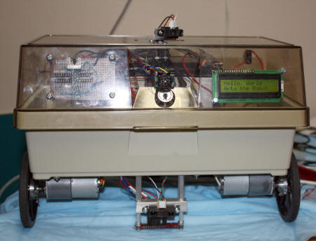
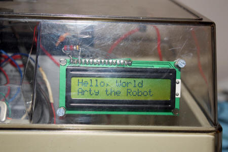
Arty the RobotA robot made from an old
|
 |
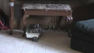
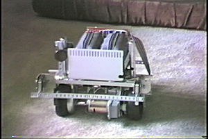
YouTube video of it rolling around the house on 9/7/10. |
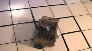 YouTube video of robot now programmed to go thru a maze
|
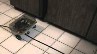 YouTube of first ine follower code
|
Intro -Arty the robot - design and build started July 2010I had built a robot (Mikey) 20 years ago from spare parts I had and using the 8052 BASIC chip. I built the circuits from scratch using wire warp and TTL chips. The robot had 16K RAM and 16K ROM and used an 8255 for I/O ports and had differential motor design.
|
| Design Objectives: a. Liking the differential motor design, I wanted the new robot to have
two DC motors which of course would be used to steer and move the robot. To those of you who ever thought about and/or built a robot, you know that those things are challenging enough in themselves to start with. |
|
When I built my first robot in 1980 there was no internet and
finding robot parts, especially motors and wheels was very, very hard.
When I built my last robot in 1992, the internet was a baby and it was
still very, very hard to find robot parts, especially motors and wheels.
Now it is like Christmas all the time for robot hobbyist! I could
not believe all the robotic web sites that exists now. Sites have
EVERYTHING you need to build your own robot from scratch or from a kit.
Motors and wheel, traditionally the hardest to find, are widely
available in many sizes, voltages, RPMs. You can check around
but I ended up buying almost all my stuff from
Pololu robotics in Las Vegas. Their
web site is excellent for finding stuff and they have forums where you
can ask questions if you need help. They ship fast and the prices are
good.
For me, this was one of the hardest but fun part to figure out. I looked at the robot bases on line but all were too small (couldn't hold my battery) or too expensive. There is a great web site that has more info on hobby robots than probably any other place on line, the Society Of Robots at http://www.societyofrobots.com/ If you go to no other place on line, that site you have to go to. There you will see photos of many robots built by alot of people. Some built using wood, plastic, metal and on even built on a ceiling tile (I kid you not).
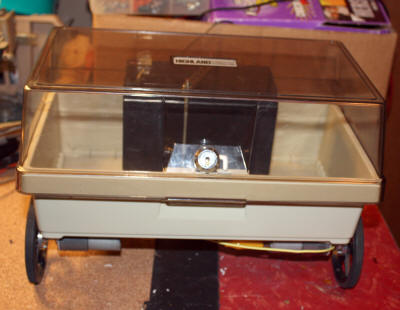
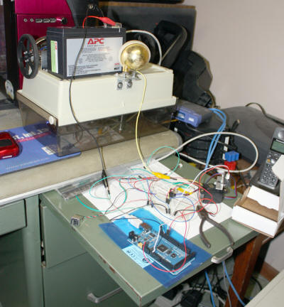
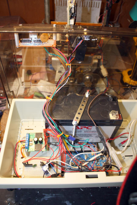
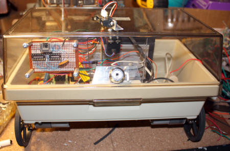
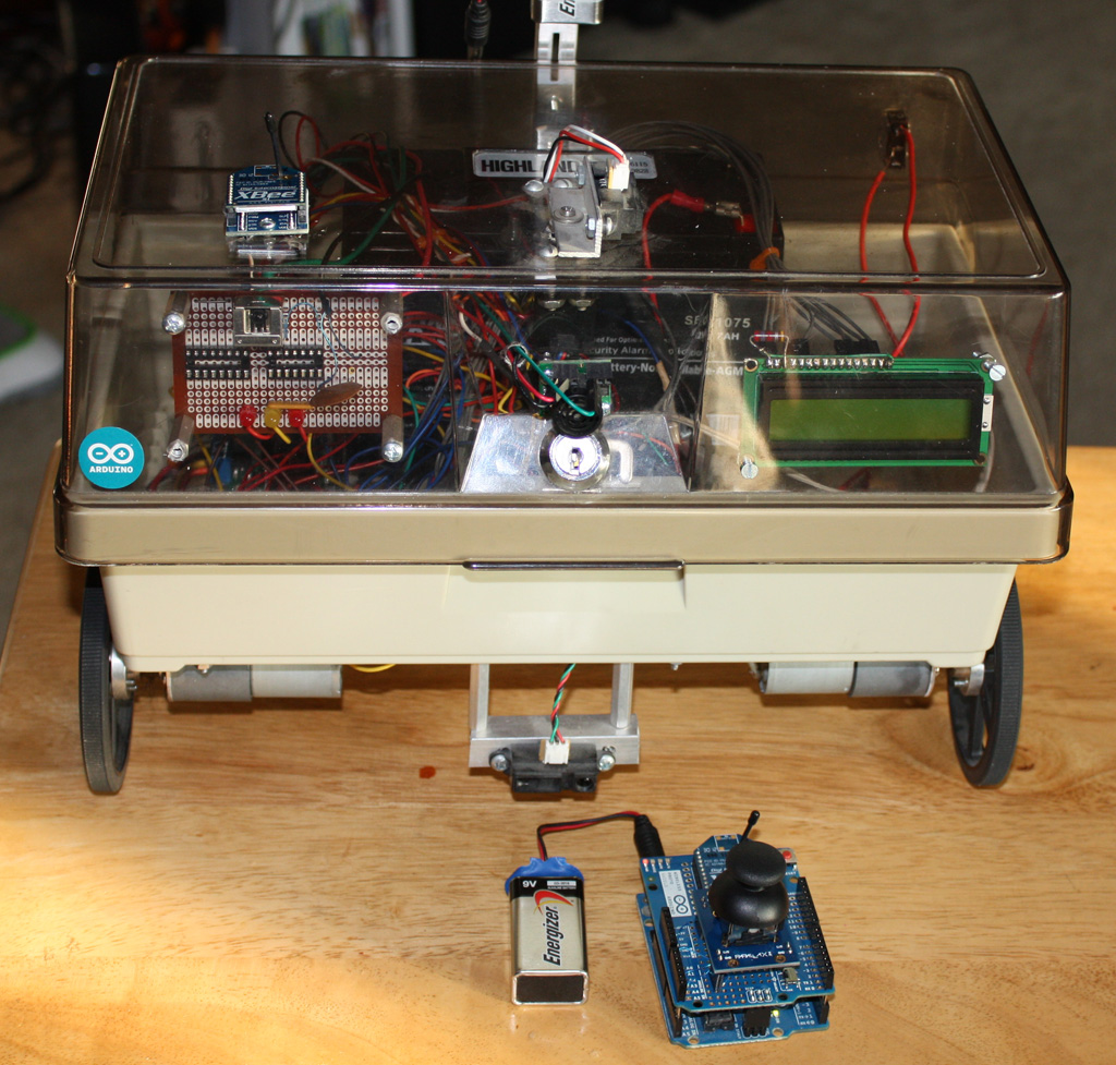
The body is one area where I felt I could be creative, used existing
parts from around my house and still be functional. So I decided to use
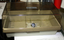
an old 5" disk storage unit I had from the 1980s.
What is sad is many people don't even know that floppy disks were 5"
when they first came out for the PC. And I bet many younger people are
not sure what even a floppy disk is anymore. Anyway, the 5" disk unit
has enough room instead to mount the battery, electronics and motors.
Since it is plastic, it is very easy to drill and light weight. Plus I
was going to throw it out if I couldn't think of a use for it! Lastly,
because it is clear, people can see all the wiring and stuff inside and
will be impressed 8-). I am thinking about putting flashing lights
inside, just like the robot on Lost In Space! If you look at the photos
you'll also see some Erector Set parts inside used to mount the battery.
There are people who have built the entire robot using Erector Set
parts!
If you look on line, you will see that the predominate robot base is
rectangular with the short sides being the back and front. My robot is
the opposite with the long side being the back and front. You need to
decide what aspect ratio works for you. If you are concerned about tight
spots, go with the smaller narrower width. If you want side to side
stability, go with the wider front. I don't think it makes alot of
difference.
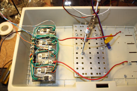
For years I didn't build my first robot because I could not find practical motors and/or wheels. I would find a motor but no way to mount a wheel to it. Or I would find one but not two identical motors. For me, the two motor and one idler wheel arrangement is the best of everything. With two motors mounted on one end and the idler wheel mounted on the opposite end, you get both directions and the ability to spin in a tight circle.
About the idler wheel...listen up...
Robotic books are great. I
have about a dozen books on robotics, some going back to 1980. However,
to write and publish a book, you don't necessarily need to know what you
are talking about! Case in point is the idler wheel. I have seen
countless descriptions of building a robotic base using 2 motors and
idler wheel(s). I feel that 99% of those descriptions are incomplete. I
even question the authors of some of these books if they have ever
actually built what they are describing.
|
|
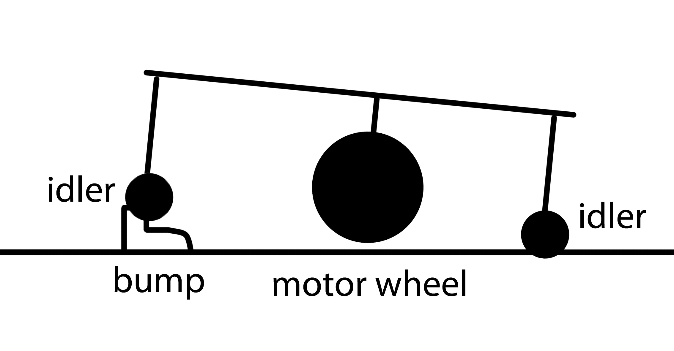
The two biggest problems with using idler wheel(s) are going over
bumps
and backing up. Regarding going over bumps, the two motor design where
the motors are mounted in the center of the base and idler wheels on
both ends has a problem going over bumps. Bumps like the metal floor
strip that separates two rooms in your house. With the idler wheels
mounted fast on the base, the robot can get caught up on a small bump.
As the first idler wheel goes over the bump, it lifts the center drive
wheels off the floor and the robot gets stuck. Been there, done that.
You could fix with springs, etc, but that's a mess. |
The second problem is 99% of the articles I have seen using idler wheels
show a SWIVEL idler wheel like you see on all chairs and the like. Big
problem. When you back up, the idle wheel swivels around so you don't
back up straight. When you go forward, the idler wheel again turns
around to face the direction of travel. While it is turning, it acts
like a rudder.
Bottom line is the robot never goes straight after a backup and you
never know for sure actually what direction it is going to head in
afterward. If you just want a robot to roll around your house, you may
not care. But if you are trying to solve a maze or follow a line, you do
care. The solution is easy. If you robot is light enough, you may not
ever need an idler wheel.
But if it does, just use a non-swivel wheel. Non-swivel wheels are harder to find. I went to Home Depot
and they had a ton of swivel wheels but only 1 or 2 fixed wheels. I had
a swivel wheel on my robot at first and had all the problems mention
above. I switched to a fixed wheel and all the problems went away. FYI!
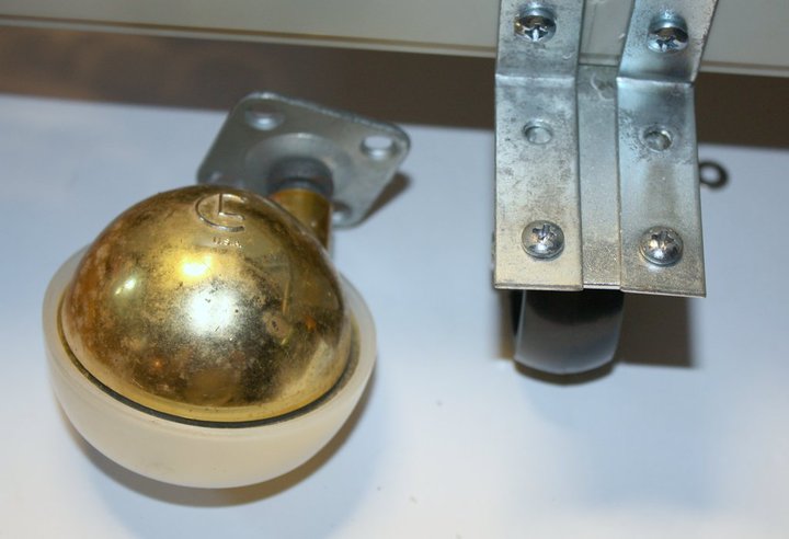 |
Use the idler wheel on the right if you want better control of direction. |
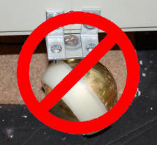
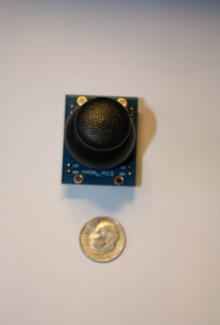
At first I tried using a small ball wheel for
the idler. Unfortunately it did not work out good, too small. So that is
when I went to the much larger swivel wheel and
then to the fixed wheel. You need to remember that the rear wheel has to
carry some weight and needs to be able to handle the stress of forward
and backwards movement and the resistance it will face on carpets, etc.
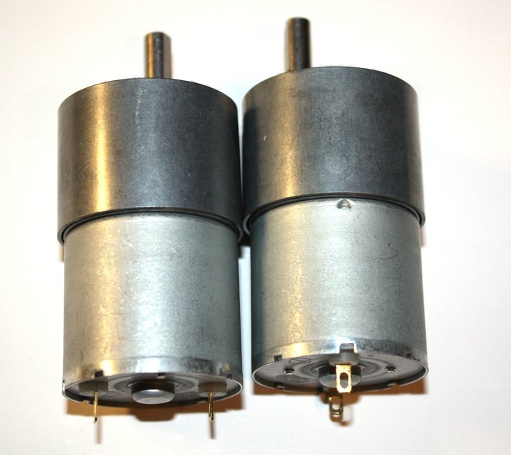
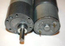 Motors -
Pololu robotics has alot of great motors. Figuring out what
size wheels I wanted help decide what RPM to choose. Using 12v DC motors
was a given for me as I already had a 12v battery and liked the
selection of 12v motors. Plus I could run a 12v motor on 6v if required.
. The hardest part for me was figuring what RPM I wanted. I was planning
on using PWM to control the speed so having a maximum RPM too high is no
longer a big concern. For the 3.5" wheels I needed
to use for the motor, I selected these puppies, 80 RPM motors. At
full speed, it moves along well and with PWM they can slow to a crawl.
See my video to get
an idea of how fast 80 RPM is with 3.5 wheels. Following lines and
doing mazes, 80 RPM is more than enough. But if I wanted a robot that
goes faster at full speed, I would next time go for a little faster,
like 100 RPM.
Motors -
Pololu robotics has alot of great motors. Figuring out what
size wheels I wanted help decide what RPM to choose. Using 12v DC motors
was a given for me as I already had a 12v battery and liked the
selection of 12v motors. Plus I could run a 12v motor on 6v if required.
. The hardest part for me was figuring what RPM I wanted. I was planning
on using PWM to control the speed so having a maximum RPM too high is no
longer a big concern. For the 3.5" wheels I needed
to use for the motor, I selected these puppies, 80 RPM motors. At
full speed, it moves along well and with PWM they can slow to a crawl.
See my video to get
an idea of how fast 80 RPM is with 3.5 wheels. Following lines and
doing mazes, 80 RPM is more than enough. But if I wanted a robot that
goes faster at full speed, I would next time go for a little faster,
like 100 RPM.
 |
TIP: Get a faster motor then what you think you need and use PWM to slow it down. It is easy to slow down a motor, not so easy to speed one up if you order one too slow! |
IMPORTANT POINT: Keep in mind also what
kind of motor controller you are going to be using!!!! If you use an
H bridge, some bridges lose alot of voltage. Your 12v
motor may end up only seeing 6 or 7 volts and going alot slower than you
expected! So you may want to go to a higher RPM motor to make up the
difference. Again, you can use PWM to slow it down but you can't make it
go faster (not using 12v anyway).
|
|
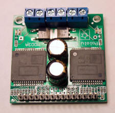
I am using this, this is the Pololu Dual VNH2SP30 Motor Driver Carrier MD03A. Works great and has no voltage loss and is easy to use with PWM. |
The motors draw 300ma free running and about 500-600ma normal running.
They stall at 5 amps but honestly, mine have never stalled. If the robot
gets caught some place, the wheels break traction and just spin in
place, the motors have never stalled on me. Each motor has a .1uf cap
across it. With my 12v battery, I can run the robot for days on a
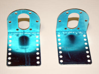
charge. They are mounted to the base with a pair of very nice
brackets that Pololu sells. Since I am not real
mechanical, I rather buy the brackets than try to make some at home.
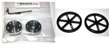
Wheels/hubs - Not being real mechanically
inclined nor having any machine shop tools, attaching wheels to the
motors has always been the biggest problem for me. Not anymore. Pololu
sells the motors and wheel and the hubs that
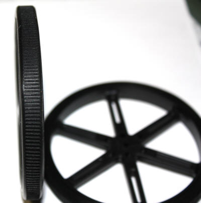
attaches the wheels to the motors so it is a no brainier now. Regarding
wheels, I got the biggest ones that Pololu sells and that mount to the
hubs, 3.54" (90mm).
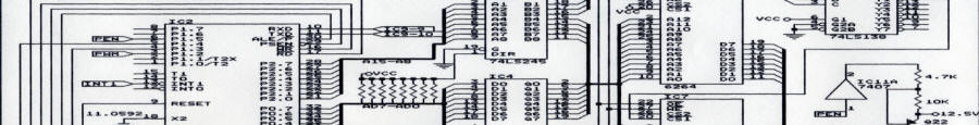
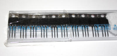
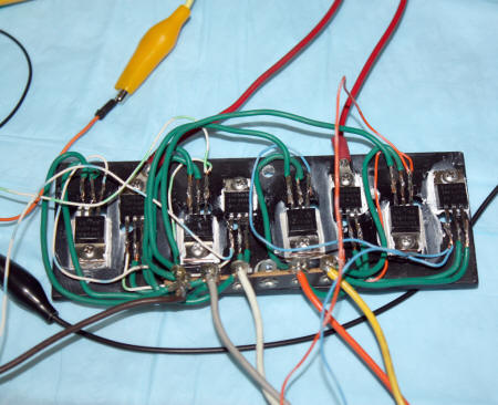
Motor Controllers -My first idea was to
build an H bridge using N channel MOSFETs. I have built
Bipolar H bridges before and they worked pretty good. The MOSFETs are
cheap, easy to work with and can easily handle the current. I have the
Robot Bonanza book and it has a schematic for an N channel H
bridge. It was similar to the circuit I had seen so many times before so
I built it assuming it would work right well. Unfortunately it didn't.
Once again I ran into the problem where people write books but have no
idea what they are talking about or don't explain things well enough.
First problem is driving the circuit. I was using the output of my
microcontroller (TTL level) to drive the gates to the controller. Didn't
work. To turn on the top MOSFETs requires alot more than 5 volts. So I
added a CMOS gate which runs off of 12v. Now the top MOSFET gate was
getting 12v. Second problem is unfortunately 12v isn't enough to fully
turn on the top N channel MOSFETs either! Gee, why didn't the book tell
me any of this? Bottom line is the motors were only seeing about 6.8v
because even though the bottom MOSFETs were turning fully on, the tops
weren't and they couldn't unless you could feed them with much more than
12v. These things you don't realize until after you have spent alot of
time building and troubleshooting the circuit. Been there, done that.
Needless to say, I am using the Robot Bonanza book as a paper
weight today.
Although I liked building the H bridge (I felt like I was not cheating
here), it wasn't going to work unless I redid it from scratch using P
and N channel MOSFETs. But I got lazy after all this and I went out and
bought from Pololu a dual motor driver board. It
can handle the stall current of the motors, has braking, is about 1/4
the size of my H bridge and like the H bridge can handle PWM and
directional control. There is very little voltage lost with it. It works
very well and has nice LED lights which show you what it is doing (adds
to the wow factor). It doesn't require any heat sink surprisingly
because the MOSFET have very little resistance when turned on.
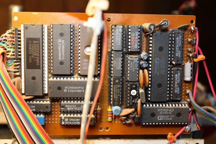
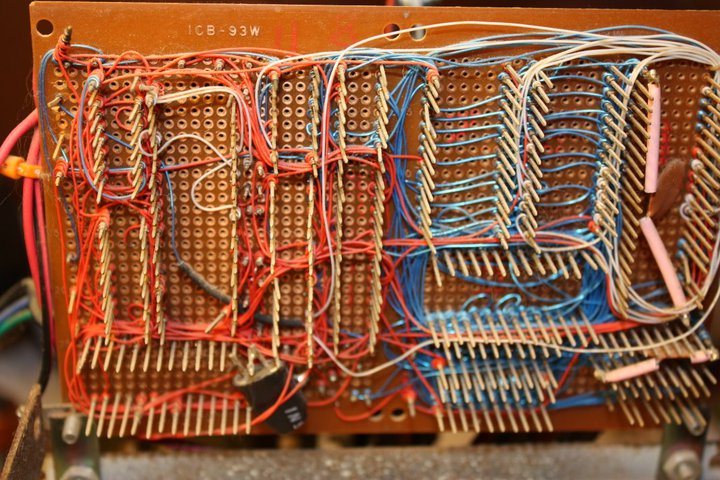
I think the biggest advance in the past 20 years is in the robot
brain, the computer. My last robot used the 8052 with on board BASIC. It
was a great chip. I built the 8052 circuit using my own design and ideas
from magazines. I had to wire up everything, the I/O, the buffers,
serial port, the memory, the CPU, everything. It took up 2 boards and
took a while to wire up and troubleshoot. Then I had to write BASIC code
for it to do anything. There were also the 6800, 68000 and 8085 CPUs
that were very popular but all had to be built from scratch. And those
chips had no BASIC so you were really on your own, having to write in
machine language. And to program them I had to use a serial port from a
PC running at like 300 baud.
Today it is awesome. Today you can get a microcontroller already made
which has EEPROM, RAM, I/O and even built in USB for alot less money
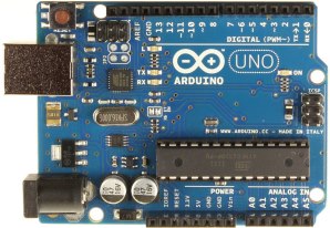
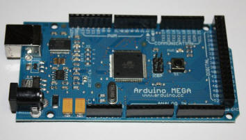
than you could buy the parts for. I decided on the
Arduino Mega microcontroller which has alot of I/O ports and much
memory. And you just plug the Arduino into your PC's USB port and you
are off programming! It can be powered off of 12v directly and supplies
5v to other stuff. Plus it has DIGITAL pins and ANALOG pins and pins
already setup for PWM and communications. And the ANALOG pins have built
in ADC! It is unbelievable what these modern microcontrollers can do.
You would really have to search far and wide to make a board that has
all of this stuff built in in the size of this and at the low price.
|
|
|
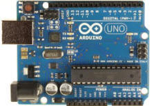
| Arduino Mega has lots of I/O pins, built-in USB, memory, etc. An excellent microcontroller. This is the brains of Arty. | Arduino Uno, a "baby" Arduino with still alot of power. I use it in the remote control as well as in many other projects. |
At first when I read that most microcontroller used "C" programming language, I stepped back and thought "C? I had been exposed to it years ago but never programmed in it. I always liked BASIC. But once I got the microcontroller up and running, I found "C very easy to learn. It is all in the syntax. And there is so many "C" programs and bits of programs on line that anyone can program in "C". "C" is powerful and well suited for robots. Plus robots don't need or use the fancy, more complicated aspects of "C" so it is easy to pick up.
Sample "C" Code
| //analog line follower 1/26/12 #include <LiquidCrystal.h> int backLight = 37; // pin 37 will control the backlight int l1, l2,l3, r1, r2, r3, tl, tr; int motorls, motorrs; //motor speed int motordir1a= 24; //motor1 direction digital pin 24 int motordir1b= 25; //motor1 direction digital pin 25 int motordir2a= 22; //motor2 direction digital pin 22 int motordir2b= 23; //motor2 direction digital pin 23 int motorspd1= 8; //motor1 speed on PWM pin 8 int motorspd2= 2; //motor2 speed on PWM pin 2 //digitalWrite(motordir1a, LOW); //go straight //digitalWrite(motordir1b, HIGH); //digitalWrite(motordir2a, LOW); //digitalWrite(motordir2b, HIGH); //digitalWrite(motordir1a, HIGH); //turn left //digitalWrite(motordir1b, LOW); //digitalWrite(motordir2a, LOW); //digitalWrite(motordir2b, HIGH); //digitalWrite(motordir1a, LOW); //turn right //digitalWrite(motordir1b, HIGH); //digitalWrite(motordir2a, HIGH); //digitalWrite(motordir2b, LOW); //digitalWrite(motordir1a, HIGH); //stop //digitalWrite(motordir1b, HIGH); //digitalWrite(motordir2a, HIGH); //digitalWrite(motordir2b, HIGH); //digitalWrite(motordir1a, HIGH); //backup //digitalWrite(motordir1b, LOW); //digitalWrite(motordir2a, HIGH); //digitalWrite(motordir2b, LOW); LiquidCrystal lcd(30, 31, 32, 33, 34, 35, 36); void setup() { Serial.begin(9600); analogWrite(motorspd1, 0); //set inital speed to 0 analogWrite(motorspd2, 0); digitalWrite(motordir1a, LOW); //set direction forward digitalWrite(motordir1b, HIGH); //set direction forward digitalWrite(motordir2a, LOW); //set direction forward digitalWrite(motordir2b, HIGH); //set direction forward pinMode(backLight, OUTPUT); digitalWrite(backLight, HIGH); // turn backlight on. Replace 'HIGH' with 'LOW' to turn it off. lcd.begin(16,2); // columns, rows. use 16,2 for a 16x2 LCD, etc. lcd.clear(); } |
What is super nice is you don't need to buy a "C compiler or anything else. There is a free Arduino programming environment that runs on your PC where you write your "C" code and then download it to the robot. It compiles and checks for errors and all kinds of neat stuff. I will be the first to say I am not a super programmer and I don't write programs to use the least amount of code or to be the most elegant. I actually write most code on the fly. With that said, attached are a couple of programs I wrote for Arty. The run around the house code. The line follower code. I am always updating the code so you never really finish writing code.
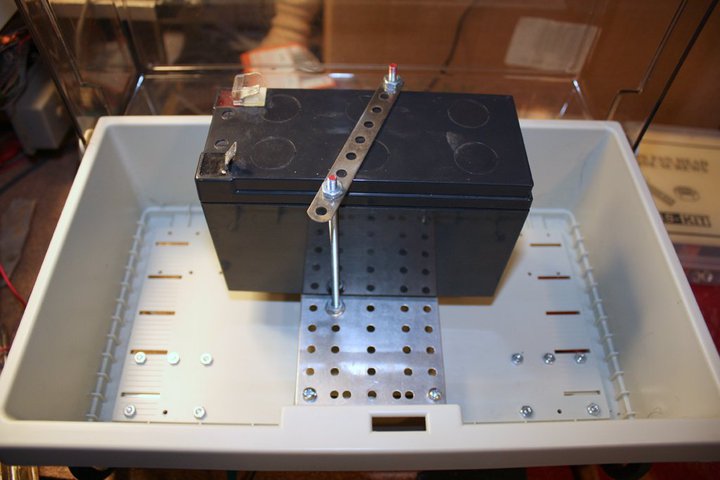
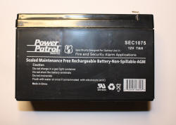
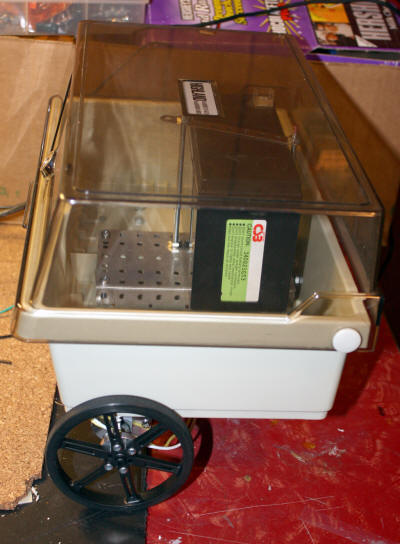
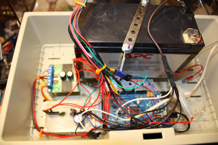
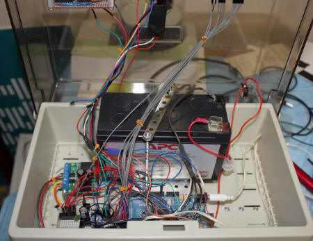
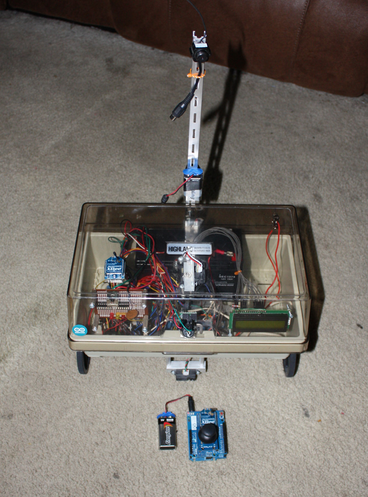
| Since I already had this very nice 12v, 7 amp hour, I designed the base and robot around the battery. The battery weighs about 6 pounds and can power the robot for a long time; I don't have to worry about recharging after 30 mins or having to replace alkaline batteries. It works for me. If I want to go very small, I would have used smaller everything, motors, base, battery, etc. If you do use a heavy battery, it would be better to use a robot with a narrow back/front and wider length as the battery placement is important for weigh distribution. If you have a short and wide robot like Arty, if the battery isn't placed right, the robot can flip over if it stops too fast. If you notice on my design, the rear idler wheel sticks out past the back of the robot to give me enough stability so I can mount the battery as far back as possible. Unless Arty tries to climb up on something, it is a very stable design. By the way, these batteries only cost like $18 on eBay. |
 |
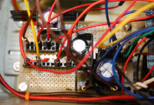
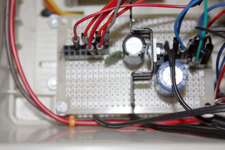
The microcontroller has a built in 5v regulator but because I plan to add lots of things to the robot, I am not relying on that. The microcontroller has one 5v and one ground pin for external circuits so I added my own 5v 7805 voltage regulators on a separate board. One 7805 can only output 1 amp, not enough so I added a second 7805. I added filter caps and pin connectors on the board and it feeds all the 5v requirements except for the microcontroller itself. My original design only used one 7805 but that was enough once I added all the new stuff.
What would be a robot if it couldn't find its way around the
house? One of the things I wanted the robot to do was to be able to roll
around the house autonomously. Sensors help do that. The robot has two
type of
sensors used to move about:
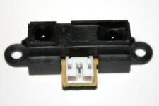
a. Sharp GP2Y0A21 IR Receiver - the robot has two
of these IR sensors. One mount on top using a servo
to sweep a large area and on below to detector low lying objects like
chair legs. The Sharp sensors have an analog output where the voltage
goes lower as the objects get farther. Conversely, as the voltage gets
higher, the object is closer. So, for example, a voltage of 1.4v says
that an object is within 10". The problem with sensors in general is
getting consistent readings. To minimize this, most people don't take
just one reading but many and average the results. Then if one reading
is off the wall, it won't adversely affect the average. The top sensor
is on a servo which sweeps about 100 degrees looking for objects up
front and off to the sides. Since the robot is so wide, this is really
needed. For narrow robots a smaller sweep may work out better. The
bottom sensor works in parallel with the top and if either detect
something, the robot takes action. There are examples of code for the
sensor all over the web.
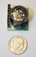
b. Maxbotix EZ0 Sonar Range Finder - when IR fails,
hopefully the sonar unit won't. Sonar has greater range but not as
accurate. It has an analog voltage output which increases as the
distance increases, 10mv/inch. So if you want to detect something 10",
you look for 100mv. It works with the IR sensors and if any of them
detect anything within range, the robot responds. The sonar unit is
mounted on the front so it won't interfere with the servo sensor on top.
|
|
|
| The robot has 2 Sharp IR sensors to detect objects about 6" and further away. One sensor is on top and the one below to detect like chair legs. | Sonar unit shoots out a wide beam to detect objects over a wide area. |
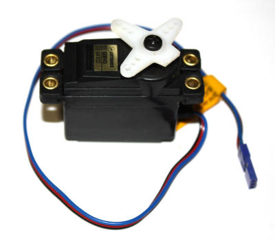
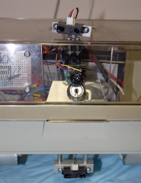
| To detect a wider ranger, the top IR sensor is mounted to an RC plane servo and it sweeps back and forth. My servo was an old one I bought years ago but rarely used. It is relatively big but it makes no difference on my robot. The sweeping is controlled by software. It is super easy with a microcontroller to tell it exactly how many degrees to sweep, how wide to sweep and at what resolution. It all can be changed in seconds. Plus the sample code to do this is included free with the Arduino software environment. | 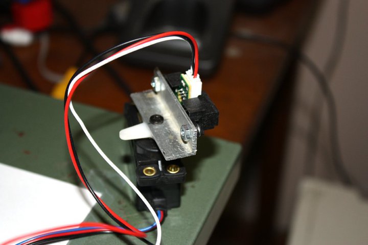 |
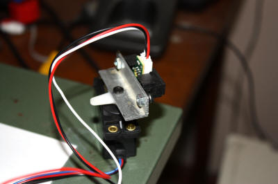
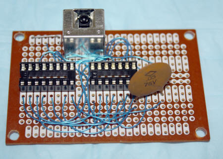
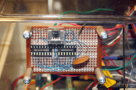
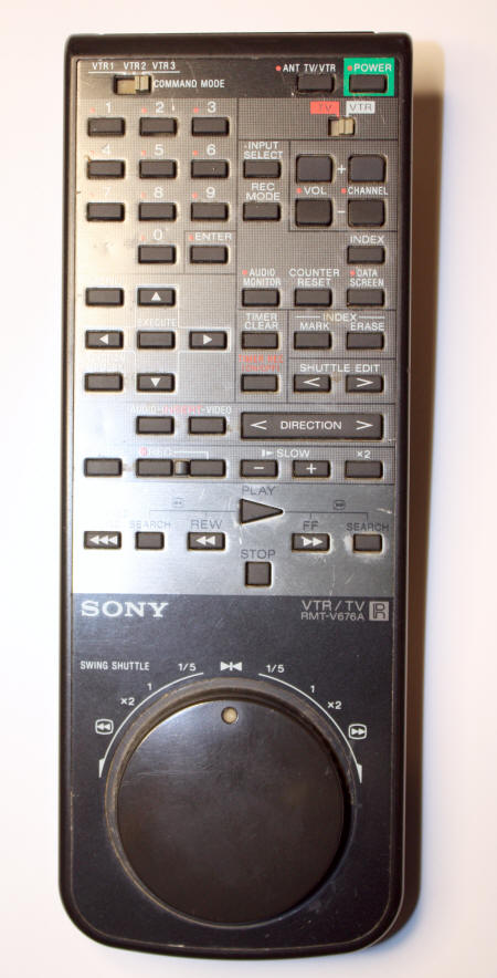
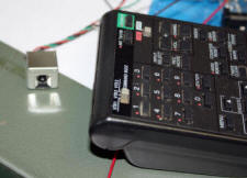
One of the most unique things about Arty is I can control him via
a VCR remote control! A few
years ago Radio Shack sold an IR receiver made to
work with IR remotes. I found one in my junk box and wired to the
microcontroller. Next I found some software that runs on the Arduino
which receives the signal from the RS IR receiver and displays the code
that was sent by the remote. I had an old Sony VCR remote not being used
so I used it to display codes for like STOP, RUN, FORWARD, etc. From
there is was easy to write a program that uses the codes to control the
robot. Since it learns codes, the software will work with any remote
control.
|
|
| On the left is the Radio Shack IR receiver I picked up years ago. I don't think they sell it anymore. The remote control is actually an old Sony VCR remote which works good because it has jog and shuttle and a bunch of other buttons. |
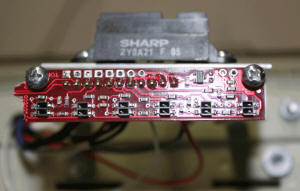
To follow lines (and mazes) I added the Pololu
QTR-8RC Reflectance Sensor Array and then the QTR-8A Reflectance Sensor Array.
They both have 8
pairs of IR LEDs/detectors used to follow lines (like .75" black
electrical tape). The sensors are .375" apart which means 2 are .75"
apart, ideal for black tape. The 8 sensors don't all have to be used and
you can break off the last 2 leaving six which is what I did. The RC
version are the "digital" ones which means you can read a zero or one (as opposed
to the analog one). However, it is not that simple to use. To use it you
have to write a "1" to each sensor, wait a certain time, and then read
the sensor. So I switched to the analog ones instead. You will then get a digital readout such as 001100 or
110000. If you are building a line follower, that is really all you need
to do. But for a maze follower/solver, it gets much more complicated.
With both software and setup. Regarding setup, the height of the sensors
above the floor is very important. Too high and the read angle is too
wide, causing 3 sensors to pick up what only 2 should. Too low to the
floor and they can strike the floor or tape on high spots. I found
around 1/8" to work pretty good.
|
|
|
| The QTR 8A sensor array; I am using 6 sensors. | Ideal output of the QTR. If the robot is over a white floor (i.e., no line), it outputs a zero. If it is over the back tape, it outputs a "1" or high signal. |
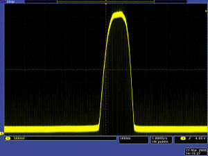
Regarding the software, I have seen a few ways to work the code. Most
seem awful complicated. The code I came with is very simple and seems to
work well for my application, 0.75" black electrical tape on a white tile
floor. What I do is very simple. There are 6 sensors connected to 6
digital pins. I read the 6 bits of data
like 000000 to 111111. So with 6 bits, if the tape is directly centered, you get
001100. If the tape is off to the left, you get 011000. Way off to the
right would be 000011 and so on. The robot then responds based on the
results. To follow a maze is alot more complicated. On a maze you can
have a 111111 which is an intersection going left to right, 111000, a
left hand turn, a 000111 right hand turn, 00000 if you go off the line
completely, etc. My software section goes over this is more detail.
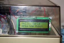
What good is a robot if it can't communicate while it is running? So I added a 16x2 LCD display. Again the code to drive it is available off the web. I use the display to show me parameters like sensor readings while it is running. It is also a great troubleshooting aid. Plus, it was cheap! The display can show both numbers and characters. I have it mounted inside the body but because the body is clear plastic it works out great. I got the display from http://www.hacktronics.com/LCDs/16-x-2-LCD-Black-on-Green.html?redirected=1.
Not yet added. Another thing I want to add is the Pololu homing beacon IR unit. It is actually 2 units, each with IR beacons at each compass heading. With one as a base, the robot will look for and home to the base unit.
Not yet added. My last robot had a great voice synthesizer, you would send it a text word and it would pronounce it. They don't have anything exactly like that now but they do have circuits that can record and speak x number of words under different conditions. Different web sites sell voice chips, some for less than $20. The problem is they all sound like crap; the are very hard to understand. When it comes to voice technology, it is far, far behind the rest of the robotic field.
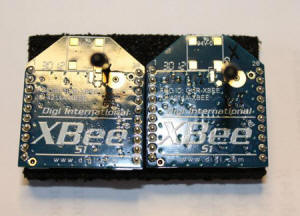
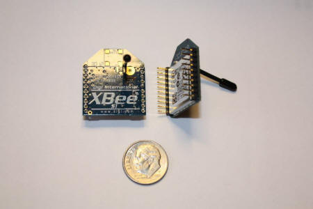
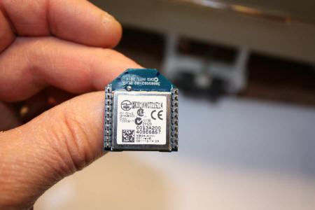
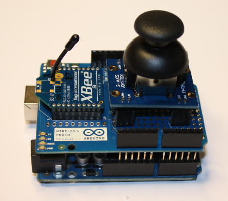
The latest modification to the robot has been the addition of Xbee
radios. These 2 way, 2.4 ghz radios can operate up to 300' and can
transmit all kinds of data. I have one mounted on an
Arduino Uno which I use as a transmitter and I have one Xbee mounted
in the robot. The robot Xbee receives commands like forward, reverse and
turn. I don't yet have the robot Xbee permanently mounted.
Another latest addition is a spy cam. I have an old 2.4 ghz wireless color video camera mounted at the top of a short mast. I am hoping to use the video cam to drive the robot around the house. Not sure of the range of the camera. It is old and low tech but we'll see.
 |
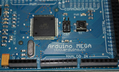 |
| The Arduino Mega, the brains of the robot. | Lots of I/O pins! |
|
|
 |
| At last, something not made in China! | Radio Shack IR receiver accepts commands for any TV/VCR remote control |
|
|
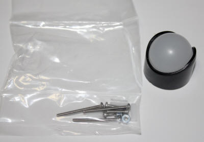 |
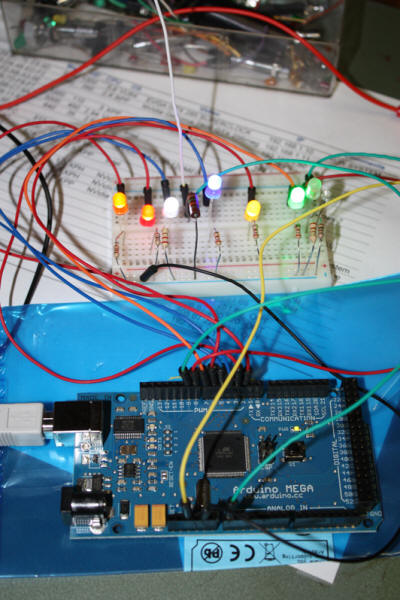
| Testing out the microcontroller with LEDs | I was going to use this 1" ball as the third wheel but it didn't work out so good. |
 |
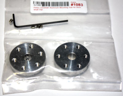 |
| Two motor mounts from Pololu Robotics. | Two wheel hubs from Pololu Robotics makes it very easy to add wheels to motors. |
 |
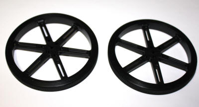 |
| Two 3.4" wheels from Pololu Robotics. | Two 3.4" wheels from Pololu Robotics. |
 |
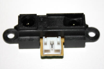 |
| Servo used to sweep the Sharp IR receiver. | The Sharp GP2Y0A21 IR receiver from Pololu. |
 |
 |
| IRF 540 N Channel MOSFETS which I tried to use for the H bridge motor control but didn't work out good. | Old 5" floppy disk storage unit to be used for the chassis. |
 |
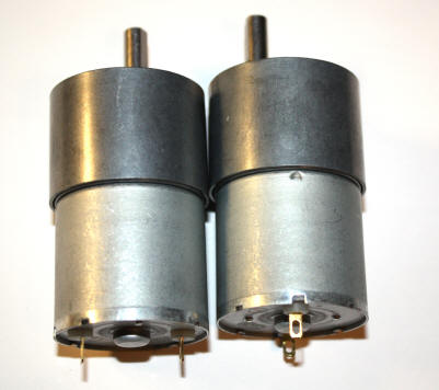 |
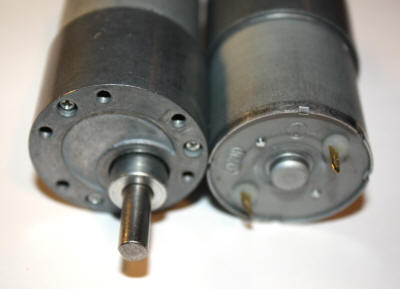
| Sharp IRR mounted on servo which sweeps 110 degrees. | 80 RPM 12 volt motors from Pololu Robotics. |
 |
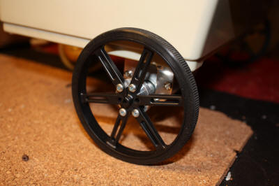 |
| 80 RPM 12 volt motors from Pololu Robotics. | Wheels mounted to hubs mounted to motors. |
 |
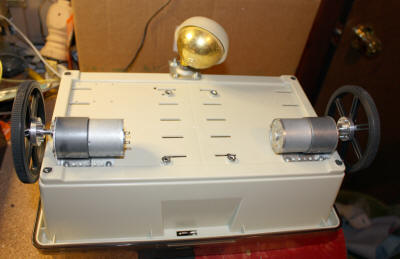 |
| Front view show battery in place. | Underside with furniture caster for third wheel. |
 |
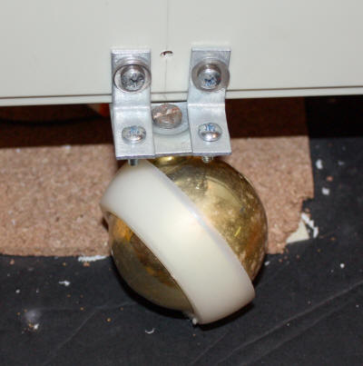 |
| Left side view. | Third wheel attached with right angle braces not good enough. See description above. |
 |
 |
| Yes, those are Erector set parts! | Bread boarding the circuits on the bench before installing. |
 |
.jpg) |
| The MOSFET H bridge motor controller circuit which I ended up not using. See above. | Experimenting with the circuits. |
 |
 |
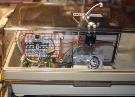
| The logic board which was to be used for the 4049 and 4011 CMOS chips used to control direction of motors. Now not used. Also mounted at top is the IR receiver for the TV remote control. | The motor controller circuit mounted in the chassis. Too bad but it did not work good enough so I replaced it with a motor controller from Pololu. |
 |
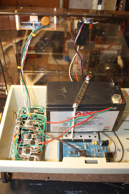 |
| Logic board mounted. | Logic board, motor controller and microcontroller mounted. |
 |
 |
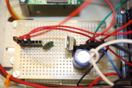
| First power distribution board design with one 7805 regulator. I updated it with another 7805 and heatsinks. | Motor controller board mounted and wired up. |
 |
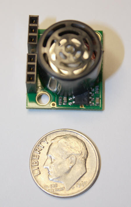 |
| All major parts mounted. | Maxbotix LV-MaxSonar-EZ0 ranger. Notice how small it is. |
 |
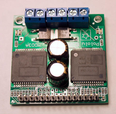 |
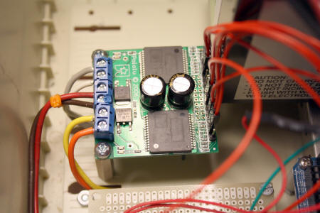
| Dual VNH3SP30 Motor Driver board with components mounted. | |
 |
 |
| The Radio Shack IR receiver is mounted on this board. | Front view as 8/30/10. |
 |
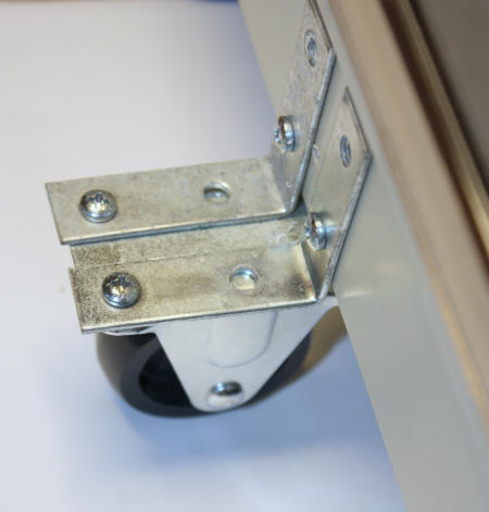 |
| Old Sony VCR remote I am using to control the robot when not in autonomous mode. | New caster wheel works much better than old one with swivel. |
 |
 |
| Old and new rear caster wheels. | Some internal wiring. |
 |
 |
| Old power distribution board now with a heat sink on voltage regulator. | Front of the robot now with 2 Sharp IR sensors and MaxBotix sonar ranger. |
 |
 |
| Front view showing Sharp IR sensor and below it the QTR-8A Reflectance Sensor Array from Pololu. | Close up view of the QTR-8A Reflectance Sensor Array. |
 |
 |
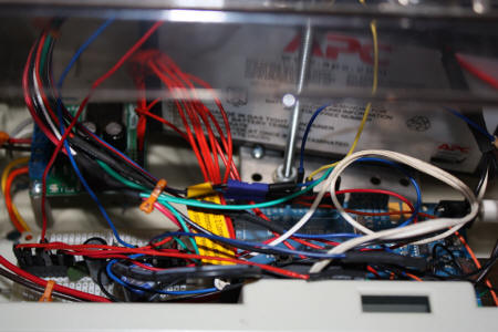
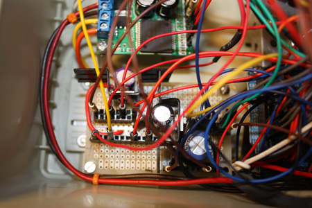
| Bottom view show the sensor array, motors and idler wheel. | Rats nest of wires, yeah! |
 |
 |
| Testing out the new display. | The robot now has an 16x2 LCD display. |
 |
 |
| LCD tucked away safe. | |
 |
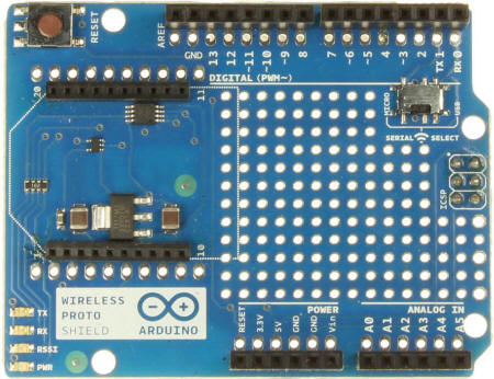 |
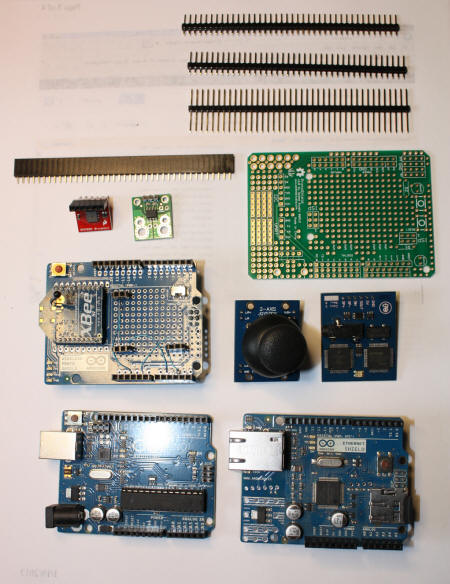
| Arduino Uno, a secondary microcontroller for remote control. It will drive one of the Xbee radios. | Wireless shield which Xbee radio will sit on which will mount to Uno. |
 |
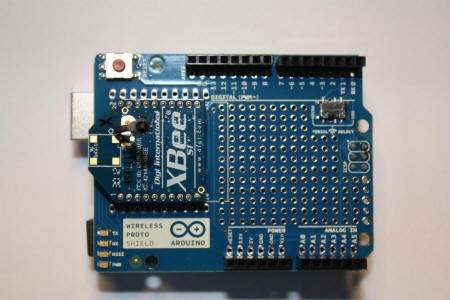 |
| Two Xbee radios used for remote control. They operate at 2.4 ghz and have a rang of about 100' inside. | Xbee radio mounted on shield. This one is used to transmit joystick commands. |
 |
 |
| These puppies are small, functional and easy to use and cost about $21 each! | Small joystick used to control robot via Xbee radio. |
 |
 |
| Joystick mount to wireless card, with Xbee, mounted on Uno. Just add a 9v battery and this will transmit the codes to the robot so it can be driven like an RC car. | Hard to see under the wires but there are now two 7805s supplying up to 2 amps of power. |
 |
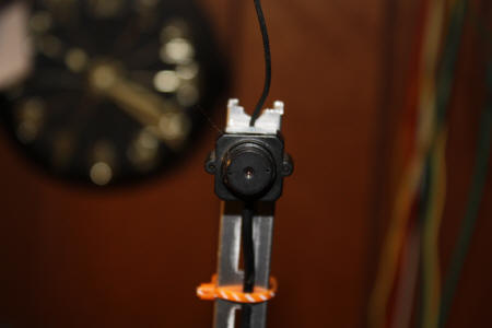 |
| I added a mast to the robot and added a wireless camera. The mounting is not finished yet. | The wireless camera is mount to the top of the mast and can help me navigate the robot via remote control. |
 |
 |
| The wireless radio part of this project is done. | Mounted Xbee radio on top to keep it away from electrical noise coming from everything down below. |
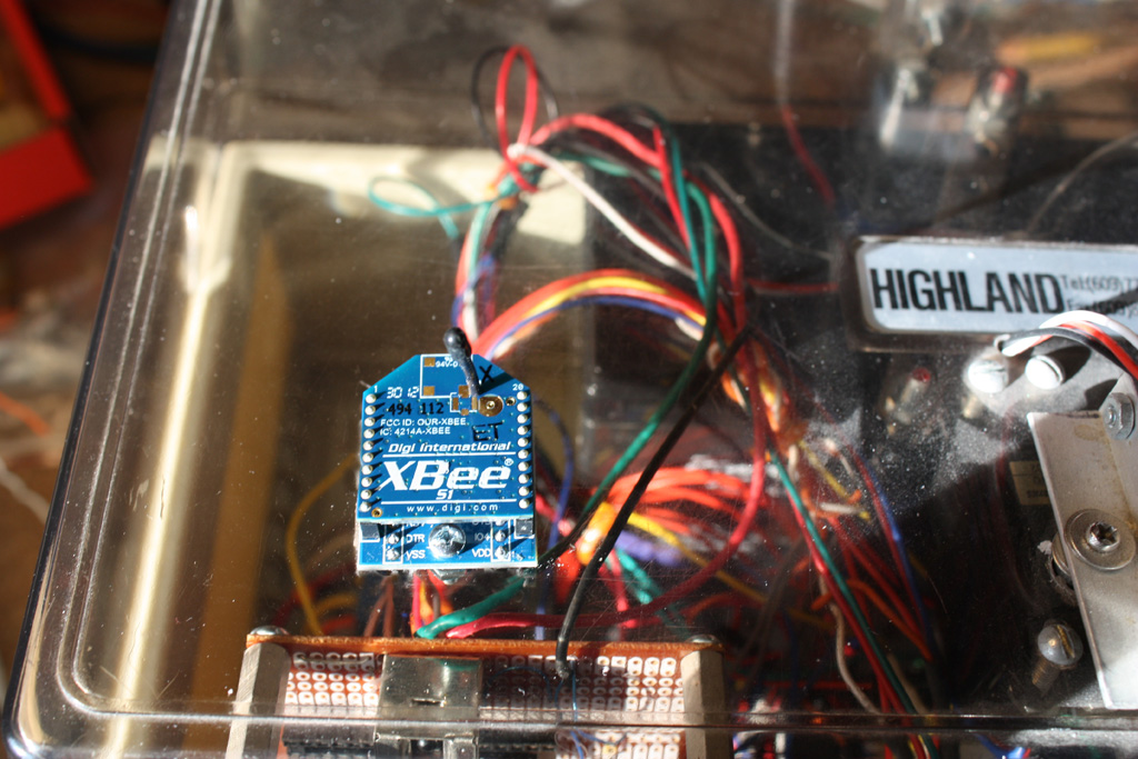 |
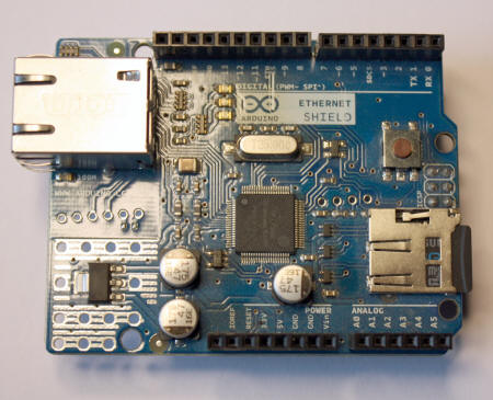 |
| Xbee radio mounted up on the "hood". | The Ethernet shield allows for any Arduino to talk over the internet. |
 |
 |
| Various shields and circuits used with Arduinos. The green board is a prototype I got from Radio Shack for $10 and includes sockets, headers, switch, etc. | The Emic voice synthesizer from Parallax. You send it a text word and it speaks it. Very easy to use and sounds pretty good. |
